|
|
Rotating Tower Systems |
|
|
"THE ORIGINAL AND STILL THE BEST" |
|
|
Rotating Tower Systems |
|
|
"THE ORIGINAL AND STILL THE BEST" |
|
Rohn 45 &
55 |
|
|
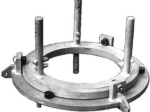
Guy Wire Bearing -- This unit allows the tower to rotate within the guy wires. It consists of an inner ring mounted in line with the tower and an outer ring to which cam followers are mounted. The cam followers ride on both the outer diameter and on the upper surface of the inner ring. These cam followers are commercially available units which have a precision needle bearing mounted on a hardened stub within a hardened crowned roller. They have two sets of seals and are lubricated through a grease fitting. Three cam followers are used for the horizontal load and three are used for the vertical load placed on the inner ring by the guy wires. Each cam follower has a rating of 11,000 pounds. |
 CLICK TO ENLARGE 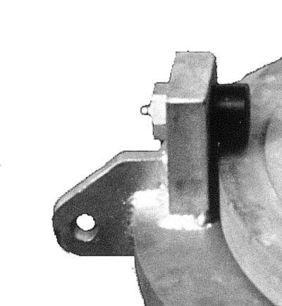
|
||
|
The guy wire attachment hole has a diameter of .75 inch in a .75 inch thick steel anchor plate. The outer ring is 1.00 inch steel as are the vertical uprights which house three of the cam followers. The inner ring is 1.25 inch thick for the Rohn 45 unit and 1.50 inch thick for the Rohn 55 unit. The inner and outer rings are made of steel and are hot dip galvanized after fabrication. The inner ring mounts in line between two tower sections. Solid steel stubs which mate with the upper tower section go through the inner ring and are welded on both sides. The lower tower section is secured to the same stubs. This method of attachment allows for the installation of at least two tower sections above the highest guy wire bearing. This feature provides a very strong mast for mounting antennas, not to mention it can be climbed. Standard tower leg hardware is used to secure the inner ring to the tower sections. Since the outer ring is stationary, it can be the end support for wire antennas, either slopers fed against the tower, inverted vee's or the end support for other types of wire arrays. Guy ring spacing will vary between 30-40 feet for Rohn 45G and 40-50 feet for Rohn 55G. Spacing for both designs will depend on the amount of wind loading on the tower from installed antennas and the tower construction requirements in your wind zone area. (i.e. 70, 80 or 110mph) |
||
|
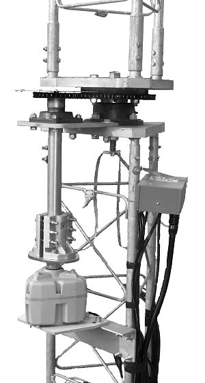
Rotating Base Unit -- The rotating base unit is installed between two tower sections either at ground level or at any height. This provides two options in designing a system. Installation of the base unit at ground level allows for easy maintenance of the rotator and base unit. If the rotating base unit is installed at an elevated level, a reduced number of guy wire bearings can be used. Separate designs exist for 45 and 55 tower to be in line with the different load capabilities of each. Each rotating base hardware set includes:
|
|
|||
|
The standard rotor bracket is set for the Hy-gain HDR-300 rotor. A bracket for the M2 Orion or a Prop-pitch rotor can be supplied in place of the standard bracket. Please specify the type required when ordering a system. With the grounding kit, direct DC and RF paths across the rotating base unit are provided. This provides a static discharge path and allows the tower to be shunt loaded through the rotating base unit. The rotating tower can be shunt loaded for use on the low frequency bands as though it were a stationary tower. |
||
|
Tower Support Bearing -- This unit has a vertical load rating of 21,000 pounds, but will not fail until a much higher load is reached. It has seals and is lubricated through a grease fitting. The bearing can be replaced using the same installation tools supplied with the base unit for assembly. It is commercially available and is used on both the 45 and 55 base units. |
 CLICK TO ENLARGE |
|||
|
Drive Shaft Bearing -- This bearing has a load rating of 4,450 pounds. It's a commercially available unit with seals and is lubricated through a grease fitting. |
 CLICK TO ENLARGE |
|||
|
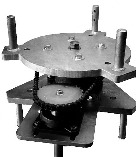
Drive System -- The drive sprocket under the tower is a 60 tooth #50 chain flat plate unit. The sprocket on the drive shaft is a 30 tooth #50 chain unit. Both sprockets are nickel plated. The drive chain is a #50 single row roller chain with a load rating of 6,100 pounds. The use of these sprockets results in a 2:1 gear reduction for increased turning torque and decreased rotational kinetic energy during operation. The standard rotor mount is designed for an HDR-300, but is easily modified to accept a prop-pitch motor or other large rotor. (Several systems have been installed using prop-pitch motors.) A rotor indicator modification kit for an HDR-300 is supplied with the base unit to correct for the 2:1 gear ratio. |
 CLICK TO ENLARGE  CLICK TO ENLARGE |
|||
|
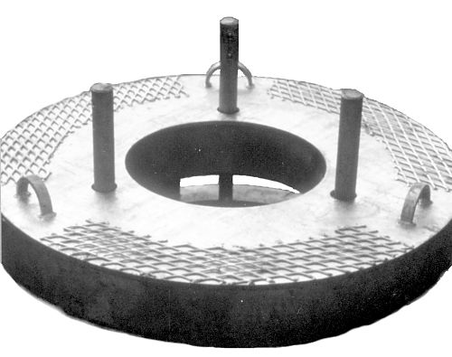
Ice Shield -- The ice shield covers the guy bearing assembly and prevents ice build-up from affecting the towers ability to turn. The shields are made from 10 gauge steel and have anti-skid diamond mesh on the top surface for the climbers safety. The guy ring and cam followers are still accessible for regular maintenance and lubrication. The shields are hot-dipped galvanized after fabrication. Separate models available for Rohn 45 and 55 tower. |
 CLICK TO ENLARGE  CLICK TO ENLARGE
 |
|||
|
The choice between 45 and 55 tower is based on the wind conditions expected, the total area and weight of the antennas to be mounted, and the boom lengths. Not only must the tower hold up the antennas, but turn them as well. Many large Yagis are not aerodynamically symmetric and can put very large twisting loads into the tower. For installations with full size 40m beams and large long boom monobanders, 55 tower should be considered. For installations with smaller monobanders and reduced size 40m beams, 45 may be more appropriate. |
||
|
Home |
Price List | Gallery
| Reviews | Customers |